| Dimensions (W x H x D) |
160 x 90 x 60 mm / 6.3 x 3.54 x 2.36 in (without fastening clip) |
| Weight |
250 g / 0.55 lb |
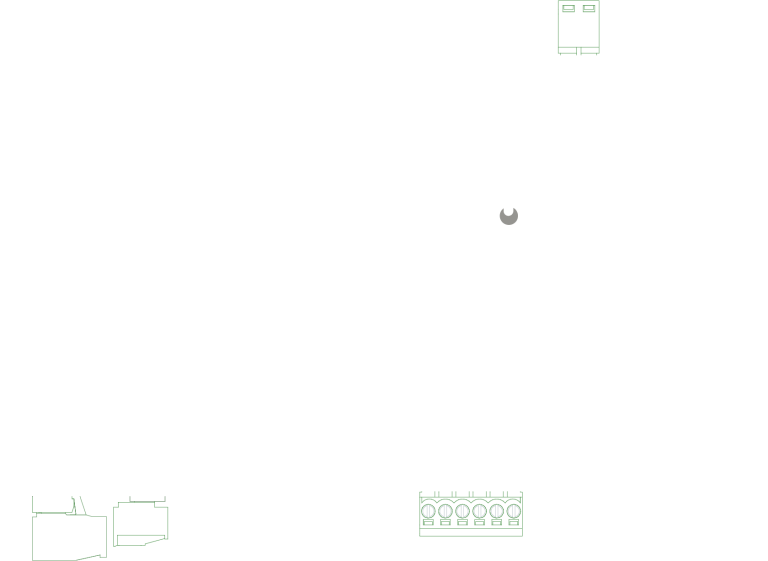
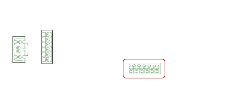
| Power Supply Input |
24 V DC on terminal plug, wire gauge: 0.2 … 1.3 mm² |
| Power Consumption |
Max. 30 W @ 4 x DALI-2 modules @ full load
7 W @ no modules
|
| Operating Temperature |
-20 … 40 °C / -4 … 104 °F |
| Storage Temperature |
-20 … 70 °C / -4 … 158 °F |
| Operating/Storage Hum. |
0 … 80% non-condensing |
| Cooling |
Fanless, convection |
| Protection Class |
IP20 |
| Electrical Safety |
SELV |
| Housing Material |
Self extinguishing blend PC/ABS |
| Mounting |
on 35 mm DIN rails (EN 60715) |
| Certification |
CE, ETL (Conforms to ANSI/UL Std. 62368-1; Certified to CSA Std. C22.2 NO. 62368-1) |
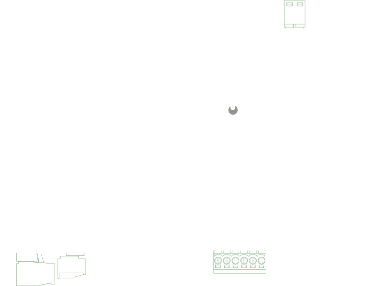
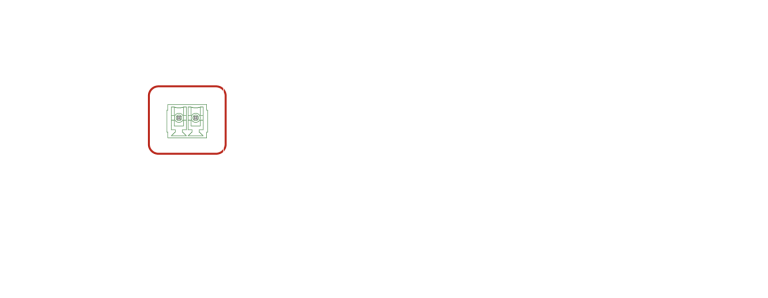
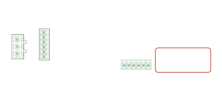
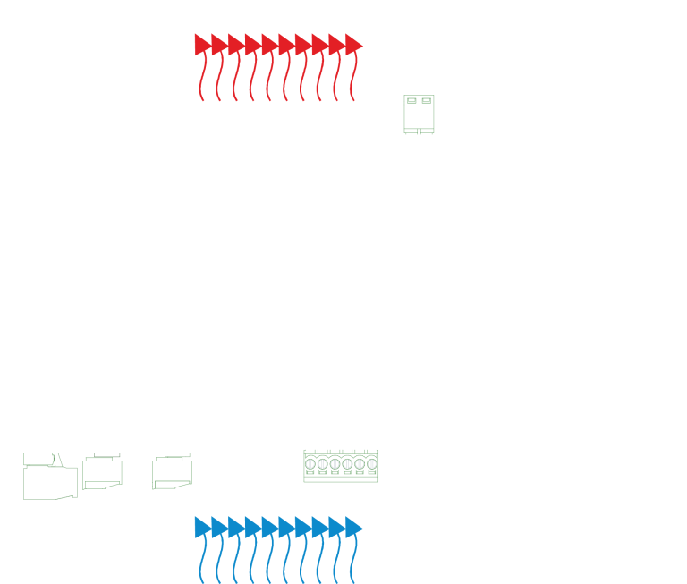
| Output Interfaces |
4 x Modular slot card, types:
DMX512
DALI-2 Module
Available Soon:
0 … 10 V / 1 … 10 V Module
SPI Pixel Module
Relay Module
RS232 / RS485 Module
|
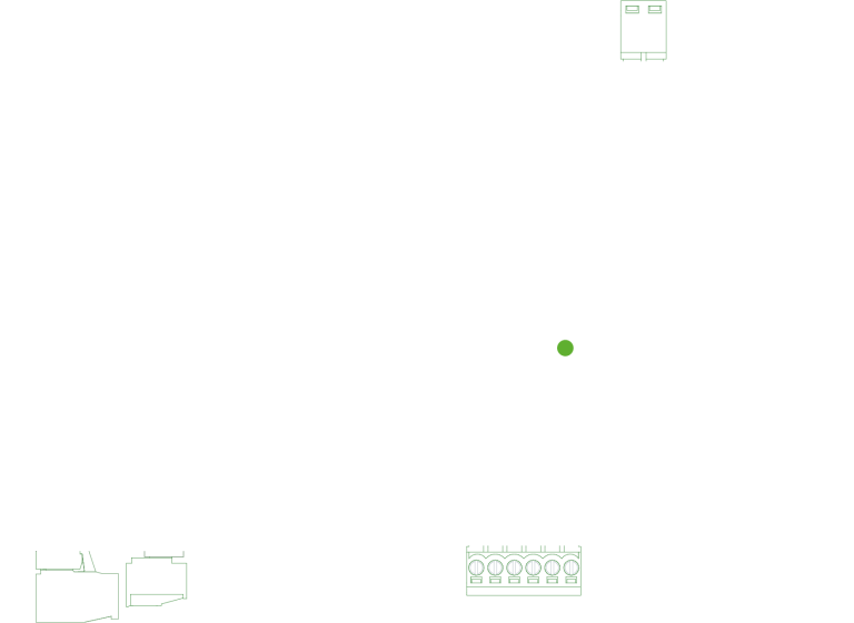
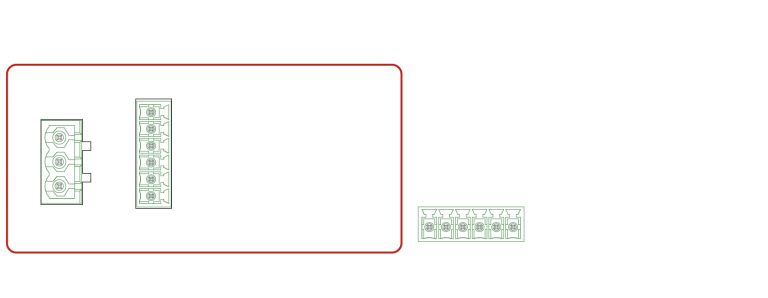
| Input Interfaces |
4 x Digital input
common ground connector
terminal plug row
wire gauge: 0.08 … 1.31 mm²
max. input voltage 24 V DC
| Input voltage |
Input current |
| 5 V DC |
2 mA |
| 12 V DC |
6 mA |
| 24 V DC |
12 mA |
12 V source: max. output current
50 mA
high level input threshold: 3 … 24 V
low level input threshold: 0 … 1 V
|
| System Interfaces |
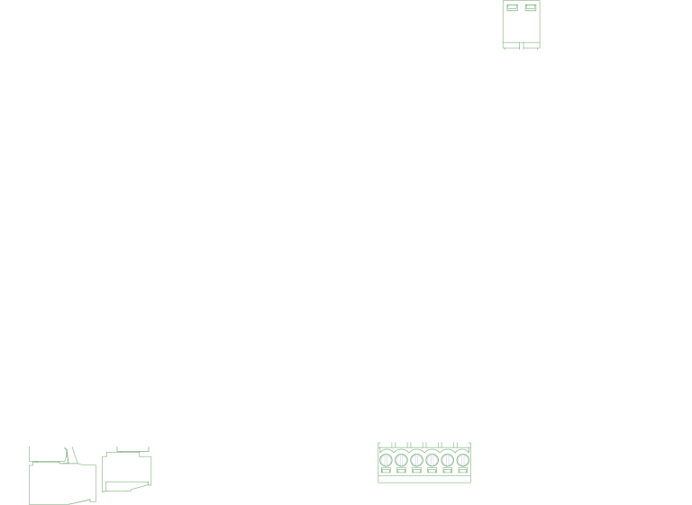
2 x e:net / Ethernet, 10/100/1000 Mbit/s, RJ45, CAT shielded
2 x USB 2.0 Type A
1 x Service port (micro-USB) |
| User Interfaces |
LEDs for Ethernet activity, device status, test pattern, power;
2 x Freely assignable versatile buttons
DMX & DALI test mode accessible with device button
1 x LED per slot card |